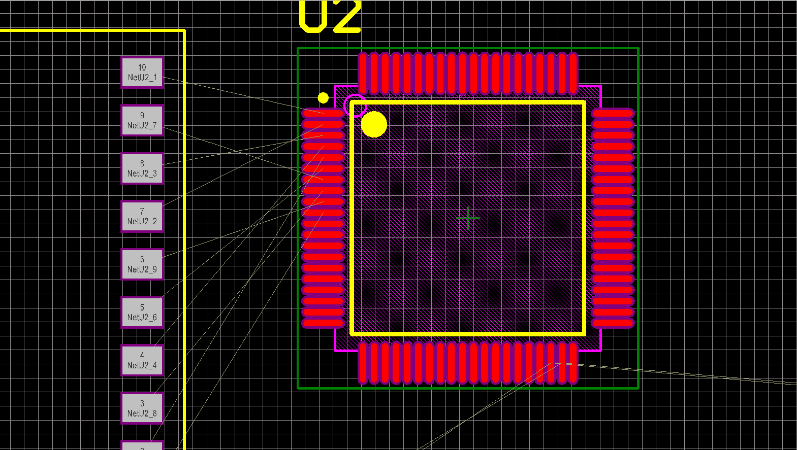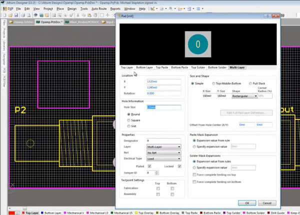
Whether PCB packaging is well established determines manufacturability of PCBs. In the process of library establishment, you'll have to find specs of corresponding components based on which your design will be capable of ensuring correctness of pin names and marks such as anode and cathode of an LED or three terminals of a transistor.Ĭlick File>New>Libraries>PCB Libraries (.pcblib) and save. As a matter of fact, few engineers use built-in library. However, if you want to establish a design totally compatible with your requirements, it's best to establish a library of your own. In the circuit of this article, switch, LEDs and socket are all contained in the circuit and symbols of these components have been maintained in Altium Designer. While in schematic diagram file, orderly establish required schematic symbols. In the engineering file, click File>New>Libraries>Schematic Libraries and save. Schematic diagram is completely through connection between schematic symbols so schematic diagram symbols should be first established. To some extent, it's more convenient to establish an engineering file.Ģ). If there's no engineering file, path to schematic diagram has to be found in the process of leading net list in PCB. If they are not put in the same engineering file, PCB and schematic diagrams will be considered to be independent from each other and net list of schematic diagram won't be automatically led in PCB file. After translation and editing of schematic diagram, net list will be led in PCB so that schematic diagram and PCB are regarded to be correlated and interactive operation can be carried out between files. One advantages of engineering file establishment lies in that it is convenient for you to administer files including schematic diagram symbol files (.schlib), PCB packaging file (.pcblib), schematic diagram file (.SCH) and PCB file (.PCB) that are all contained in the engineering file. Open Altium Designer and enter main interface.Īccording to priority, click File>New>Project>PCB Project and complete an engineer establishment prior to saving this file.

Therefore, it's first and foremost to determine the correctness and accuracy of schematic diagram design.ġ). Schematic diagram design is the basis of PCB design, correlated with effect of PCB design so that if something goes wrong in schematic diagram, some mistakes have to take place to PCBs. Then comes circuit schematic diagram and finally comes PCB design.

Then a simple design will be applied as an example to indicate PCB design process.Įverything starts with an idea. Prior to the design of a type of products, a scheme design has to be carried out, basic module of circuit planned, circuit diagram drawn, all of which can be completed manually.


 0 kommentar(er)
